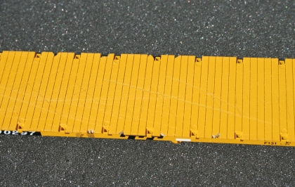
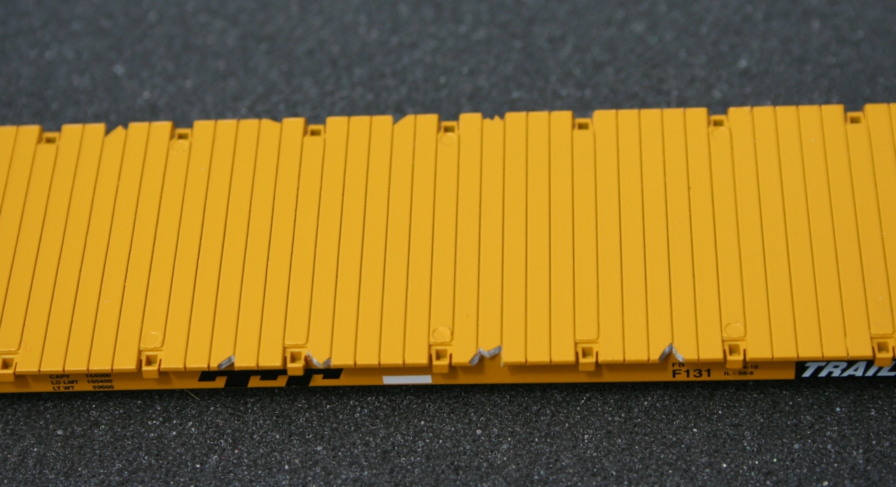
Distress the deck with a razor saw to make it look well worn. Using the lines between the boards on the deck as a guide, cut the ends of the boards with an X-Acto knife to make it look like individual boards from the side.
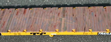
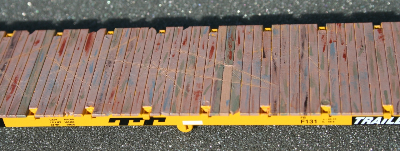
Weathered deck. Notice the gouges in the deck. The deck was painted with several colors to give it this look. Refer to the handout for complete instructions on how I did the weathering. Remember to paint the ends of the boards.

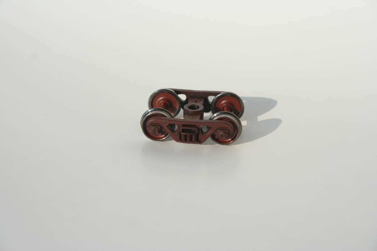
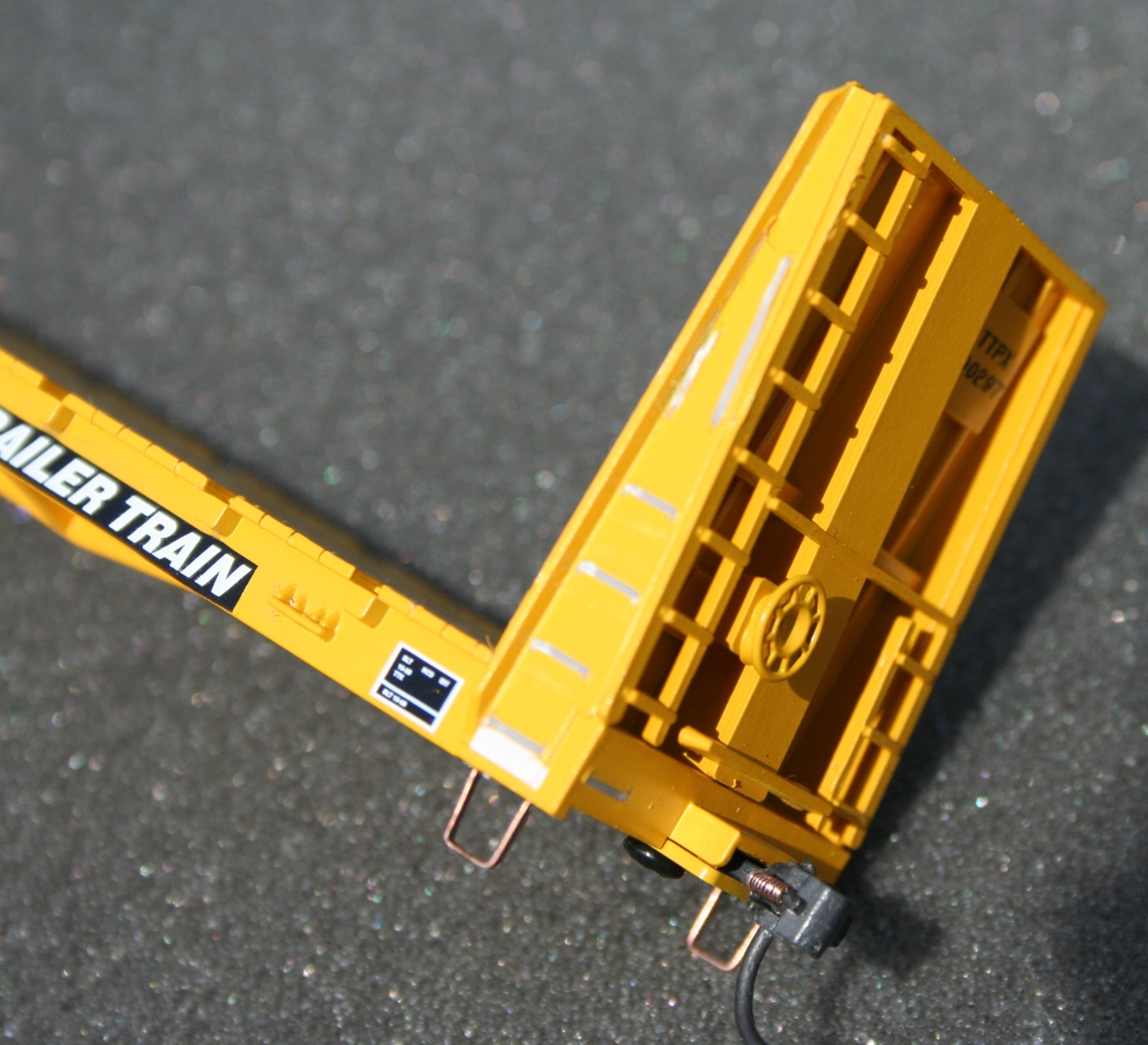
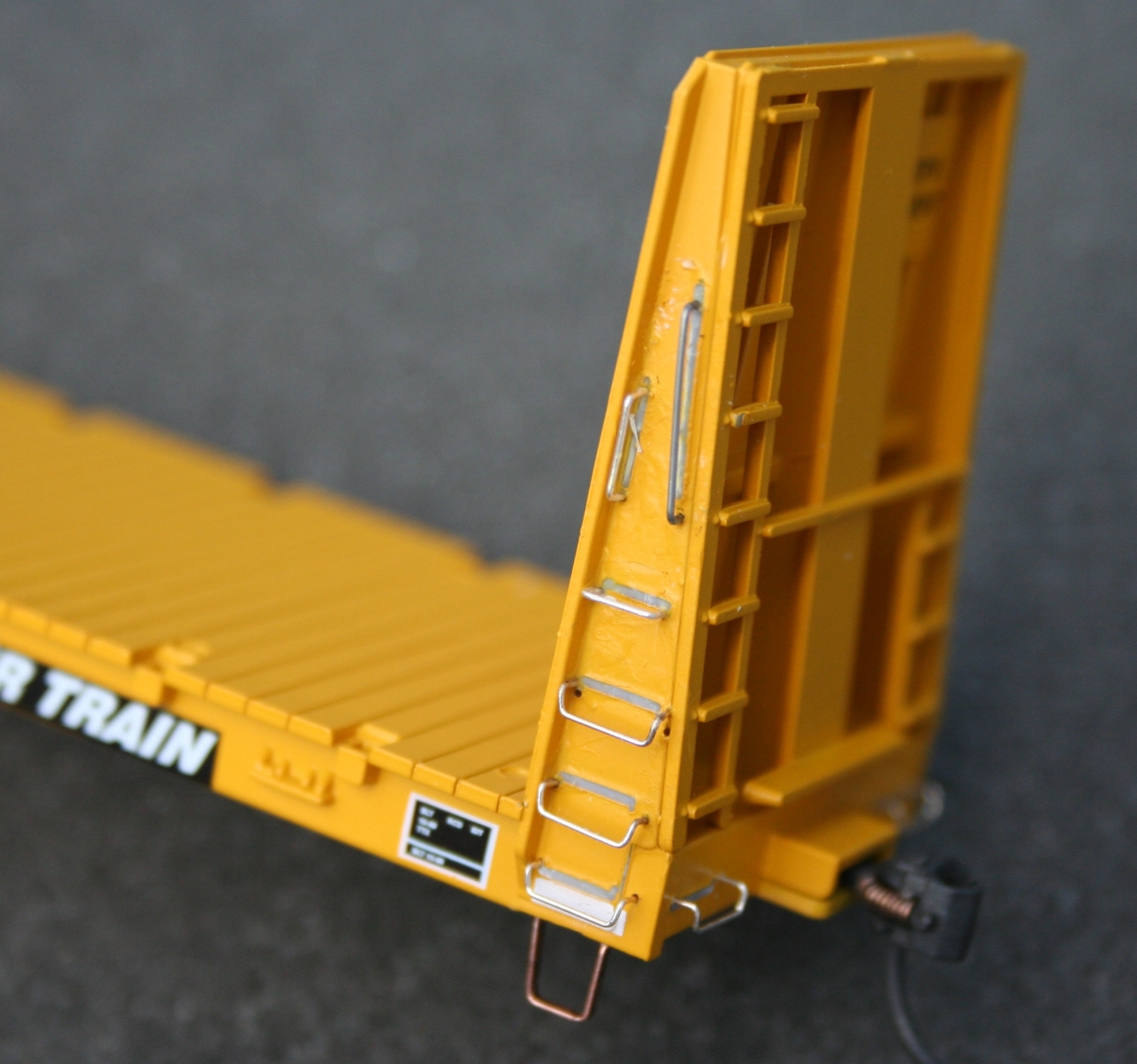
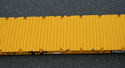
Remove all of the cast on grab irons and the stirrups. NOTE: In this picture, the stirrups have already been replaced with metal stirrups.

Install all of the grab irons. NOTE: The vertical 36 inch grab iron was hand formed.
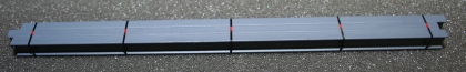
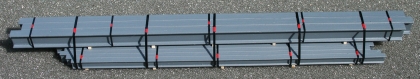
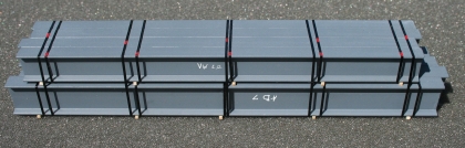
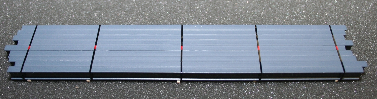
Top layer of four layer I-beam load. This layer has been painted and "banded." Don't forget to add the red "clips" on the banding.
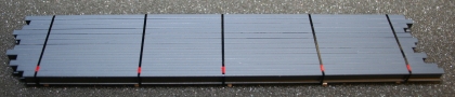
Second layer of a four layer I-beam load. Don't forget to add the red "clips" on the banding.

Third layer of a four layer I-beam load.

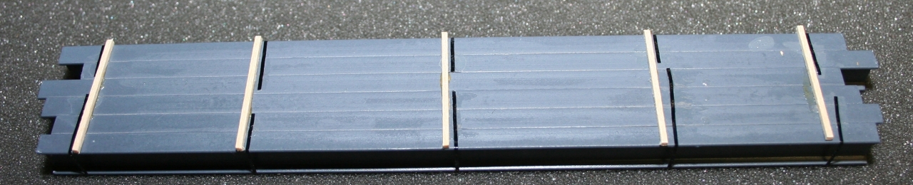
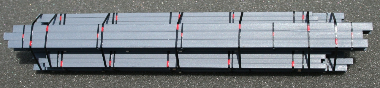
Bottom view of the bottom layer of a four layer I-beam load. This view shows how I attached the banding to the bottom of the load and how I placed the dunnage. Cover the ends of the banding with super glue to secure it to the load.
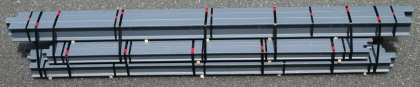
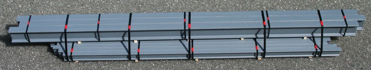
Top and second layer of I-beams banded together. When banding the layers together, do not put a band over another band on a different layer.
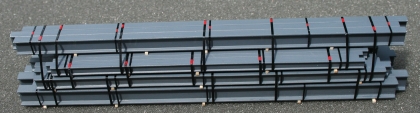
Top, second and third layer of I-beams banded together. Notice that the third layer is banded to the second layer. The only place that the top layer is banded to the third layer is on the ends of the top layer of I-beams.

A close look at the banding of the second layer to the third layer from above. Notice that I painted the red clips on the banding for layers two and three together on the opposite side from the red clips that are on the banding for the second layer.
Layer four banded to layer three. This completes the I-beam load.
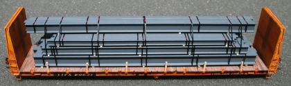
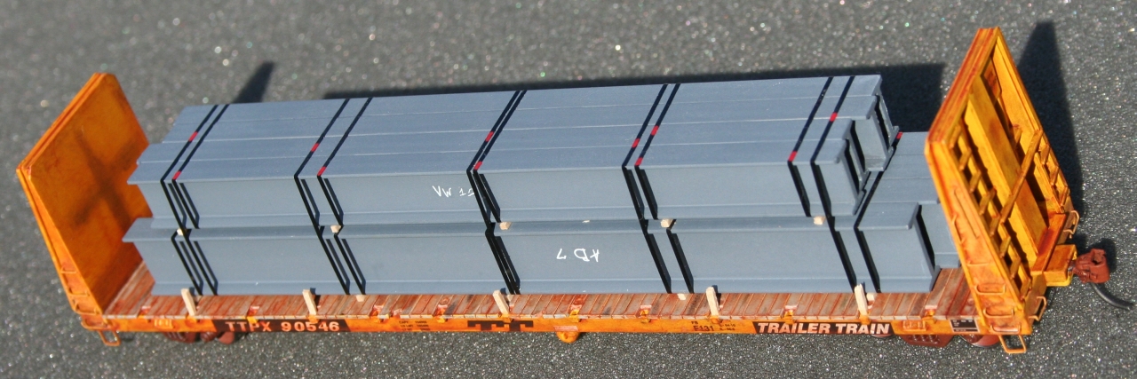
Completed model with a four layer I-beam load.
Completed model of a two layer I-beam load.

Completed model with a two layer I-beam load.
|

©2007-2023 B & FE Railroad Co. All rights reserved.
Last update to this page was July 29, 2012 |


