
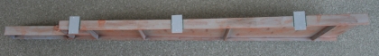
Attaching the third vertical brace to the right side of the beam.

Attaching the fourth vertical brace to the right side of the beam.

Attaching the fifth vertical brace to the right side of the beam.
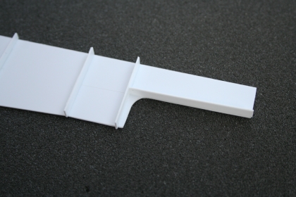
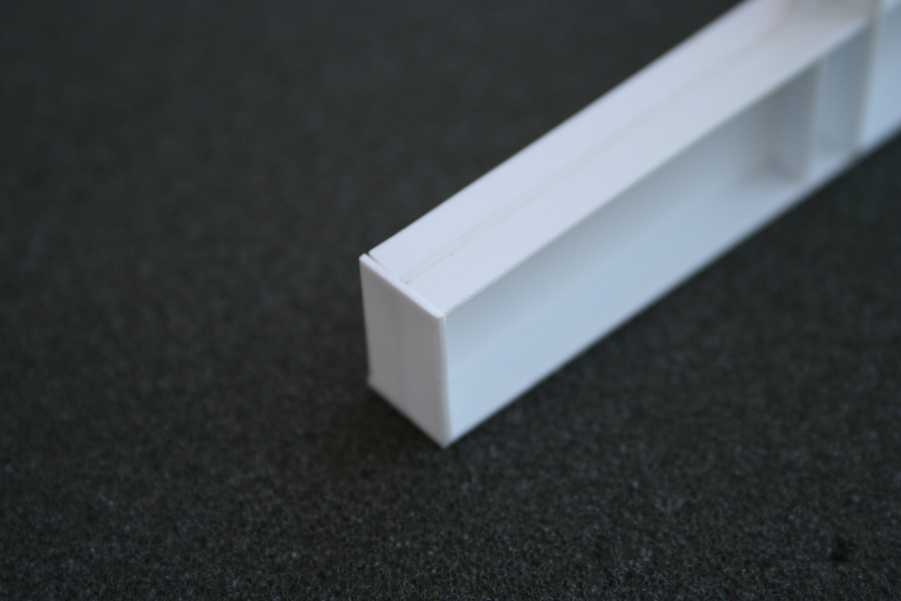
Attaching the "Top Cap" to the right side of the short end of the beam.

Attaching the sixth vertical brace to the right side of the beam.
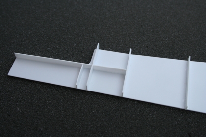
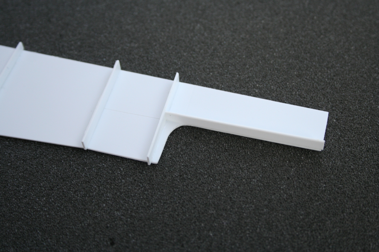
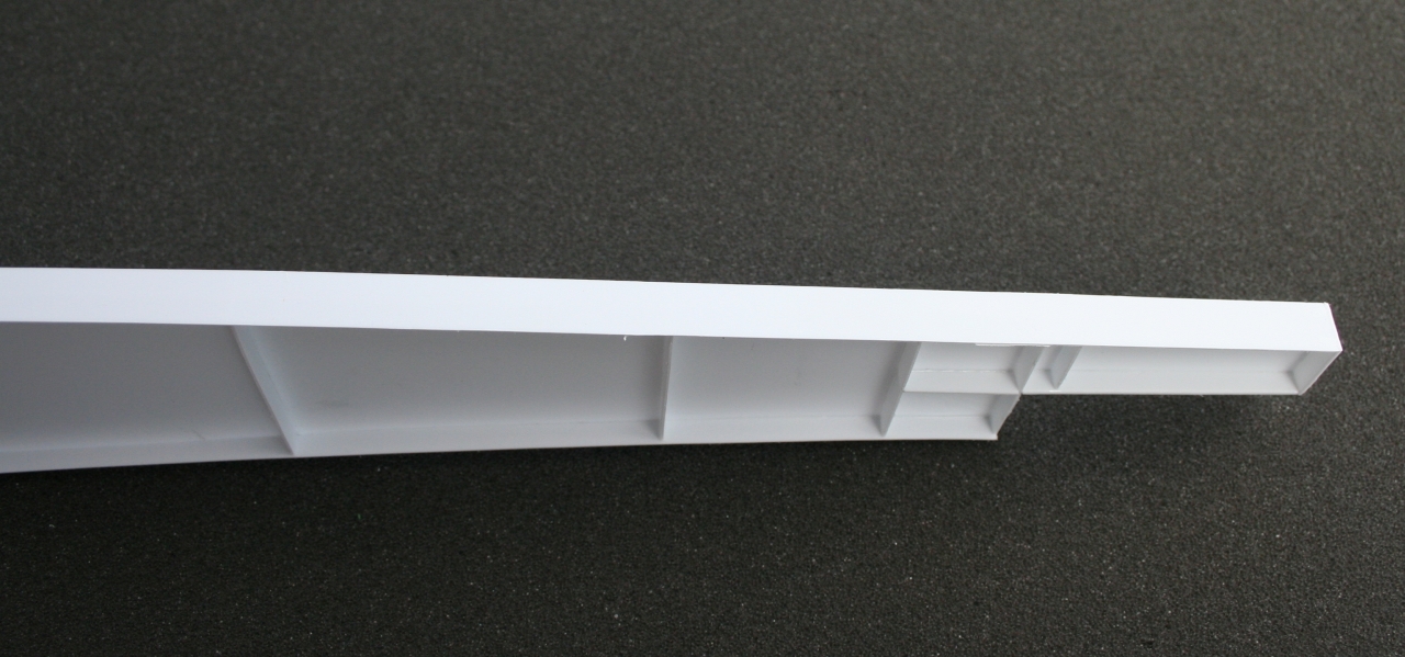
Attaching the "Top Cap" extension between the fourth and fifth vertical brace to the right side of the beam.
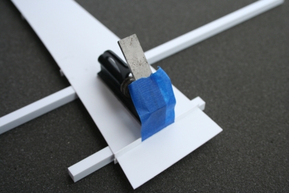
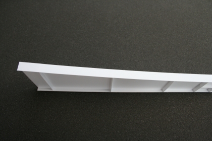
Attaching the first vertical brace to the left side of the beam. Attach all of the vertical braces, "Top Cap," and "Top Cap" extension on the left side of the beam as you did on the right side of the beam. Notice that I used scrap .250 square plastic to support the beam while working on the left side.
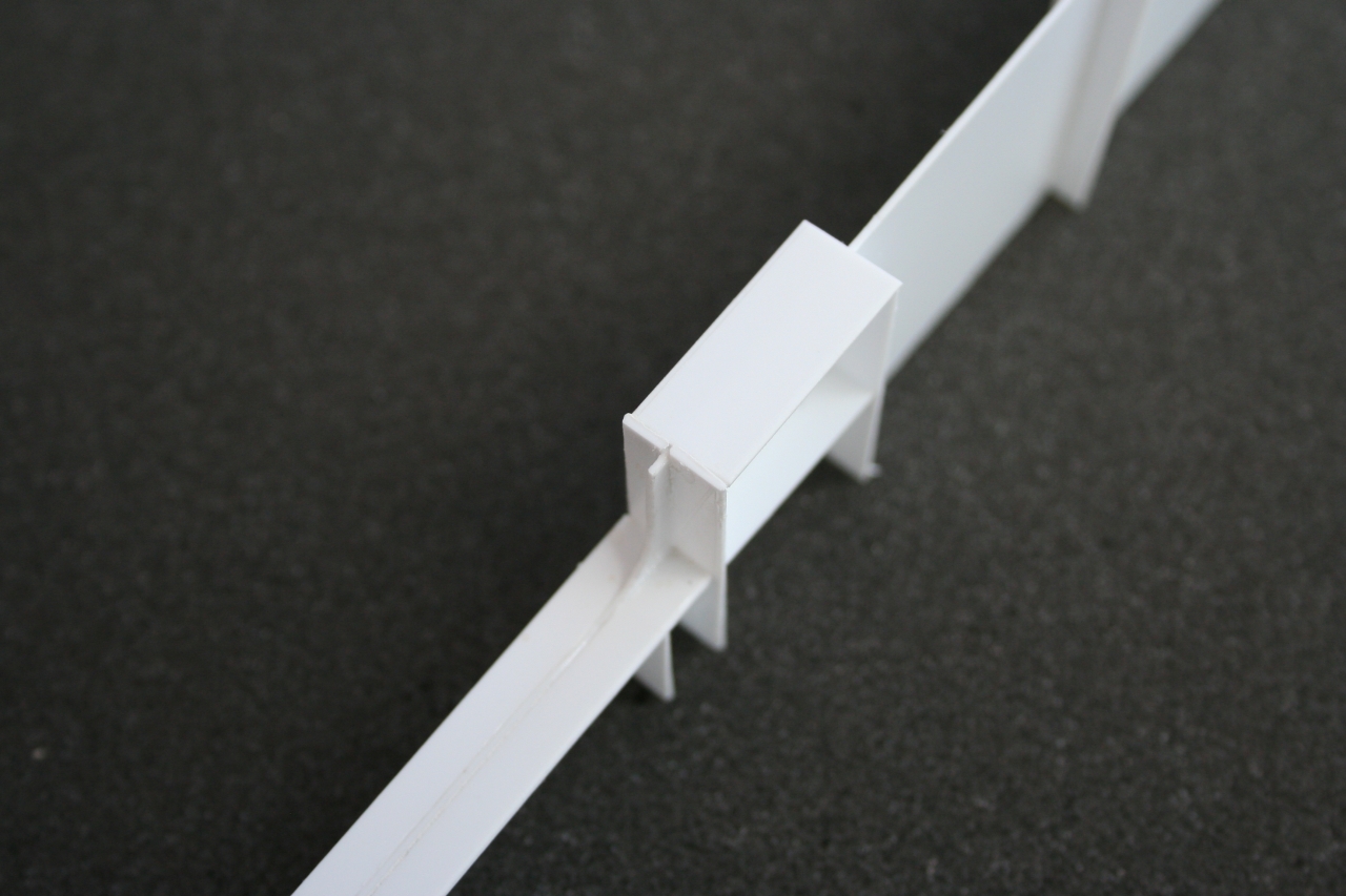
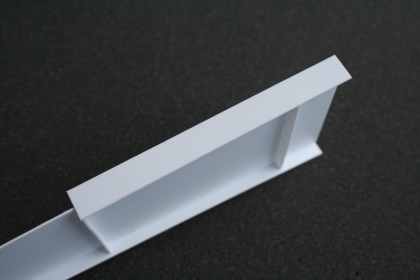
Attaching the short "Top Cap" to the beam between the fourth and fifth vertical brace.
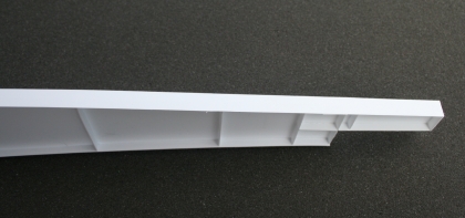
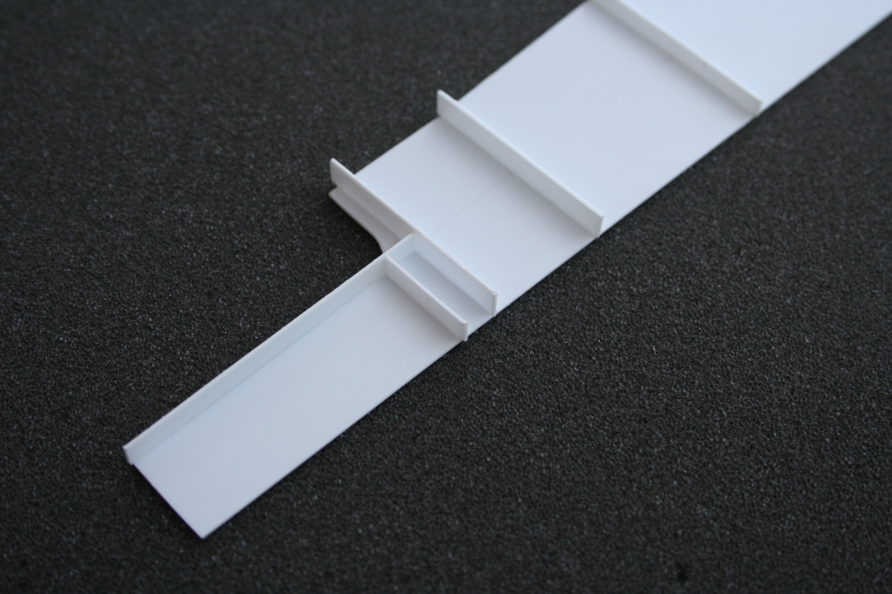
Attaching the "Top Cap" on the curved portion of the beam.
Attaching the short "Bottom Cap" on the "Big End" of the beam.

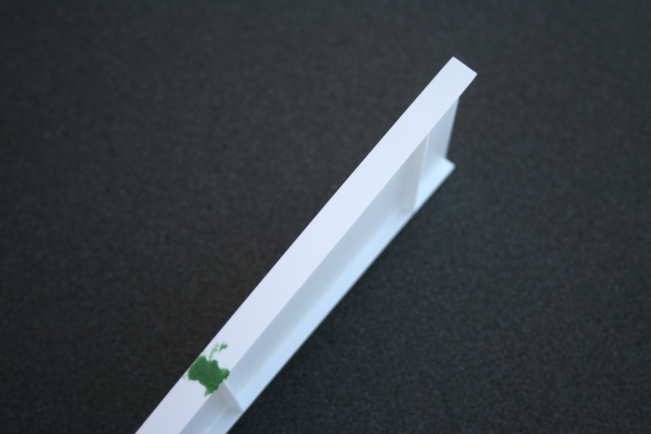
Attach the "End Cap" on the "Small End" of the beam.
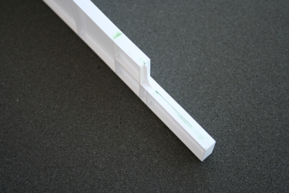
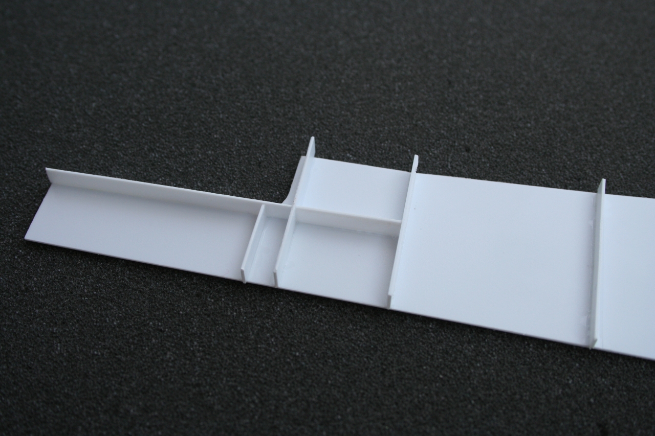
Attaching the long "Bottom Cap" extension between the second vertical brace and the "small end" of the beam.

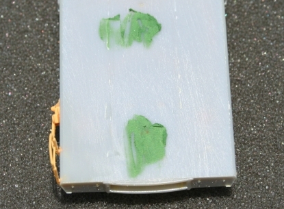
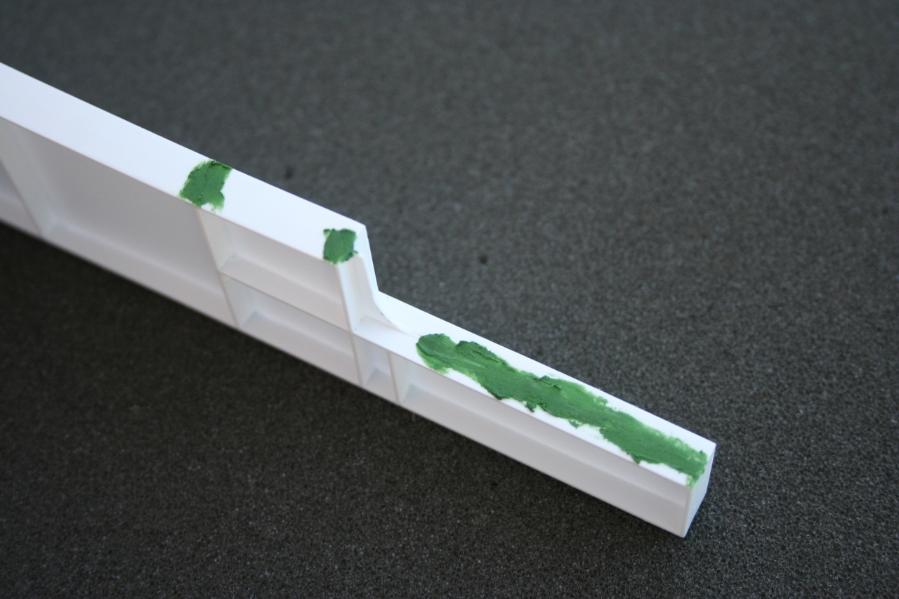
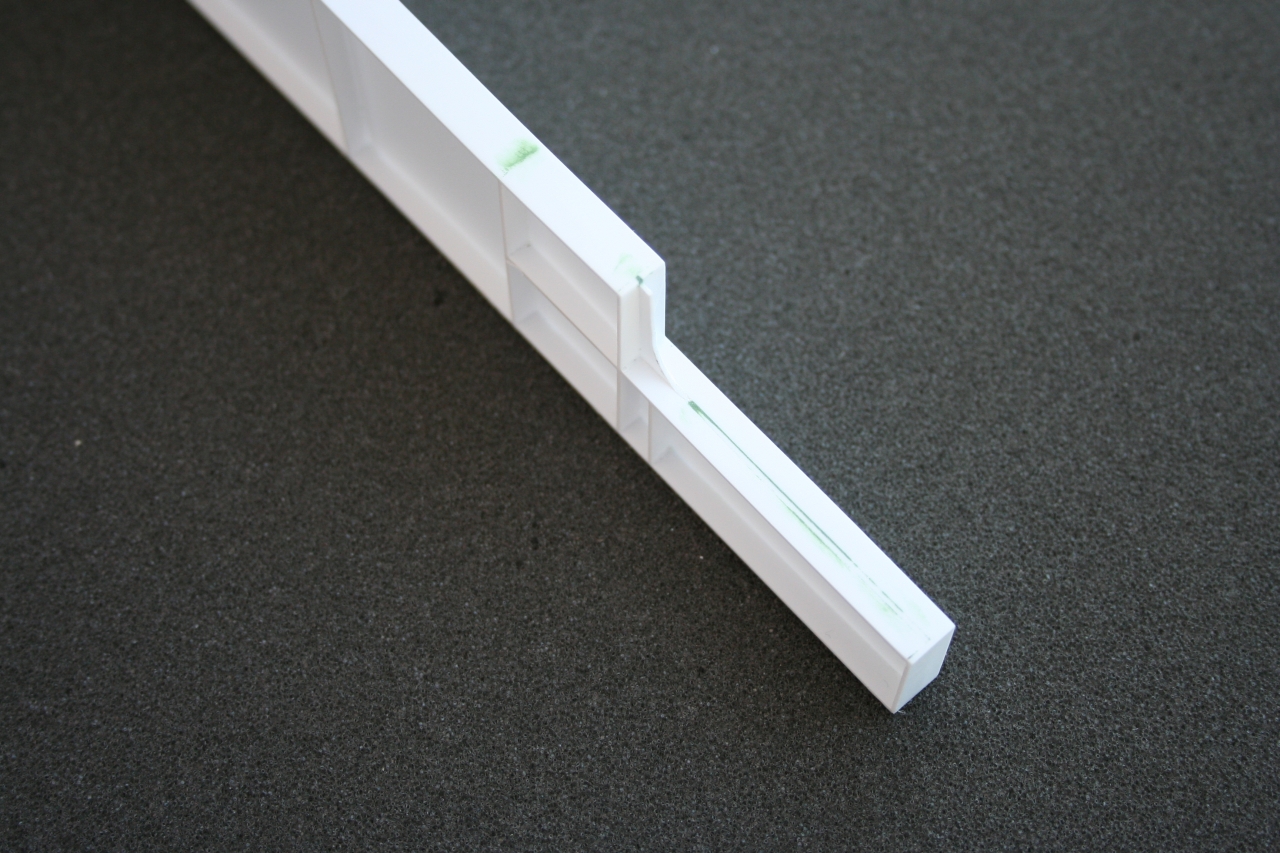
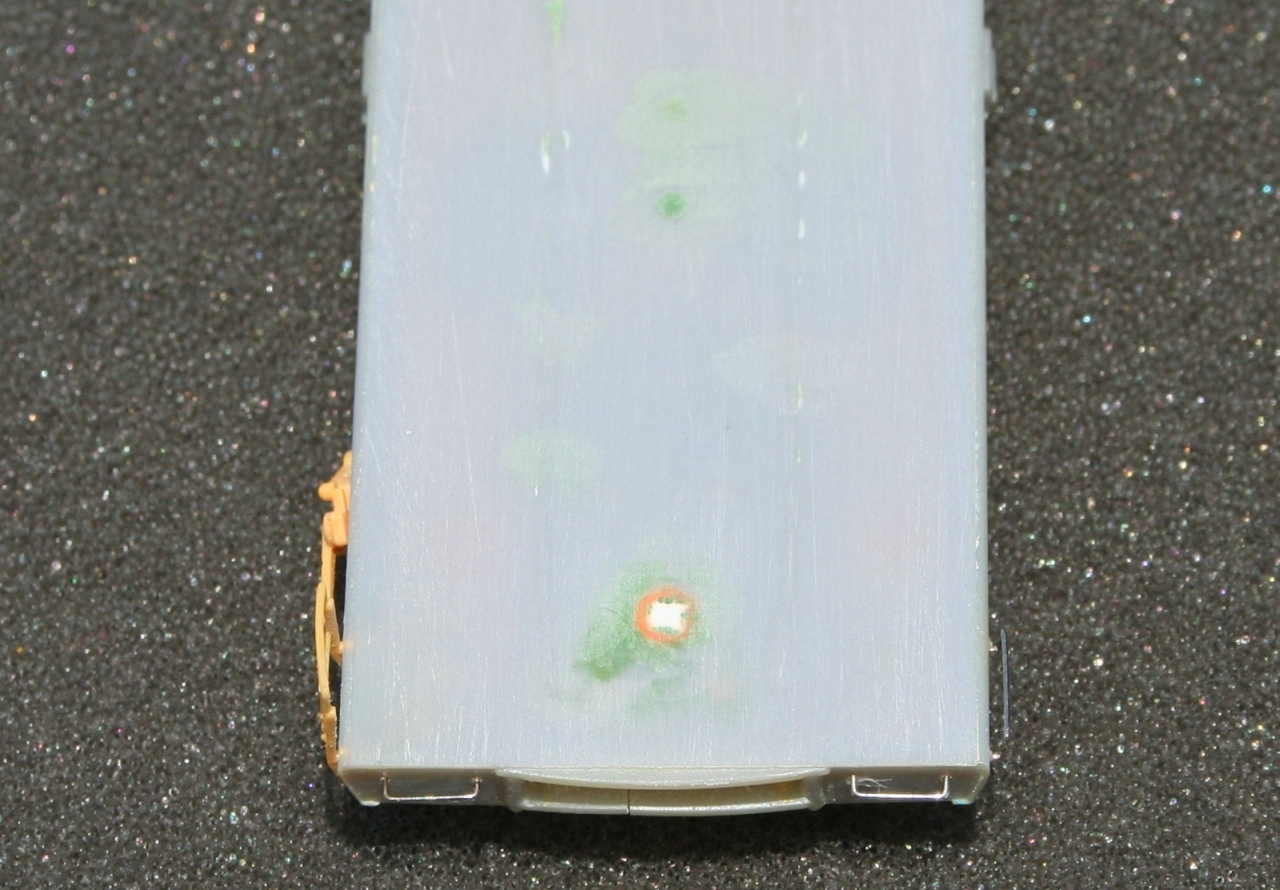
Inspect the "Top Cap" of the beam and fill any problem areas with Squadron Green Putty.

Inspect the "Bottom Cap" of the beam and fill any problem areas with Squadron Green Putty.
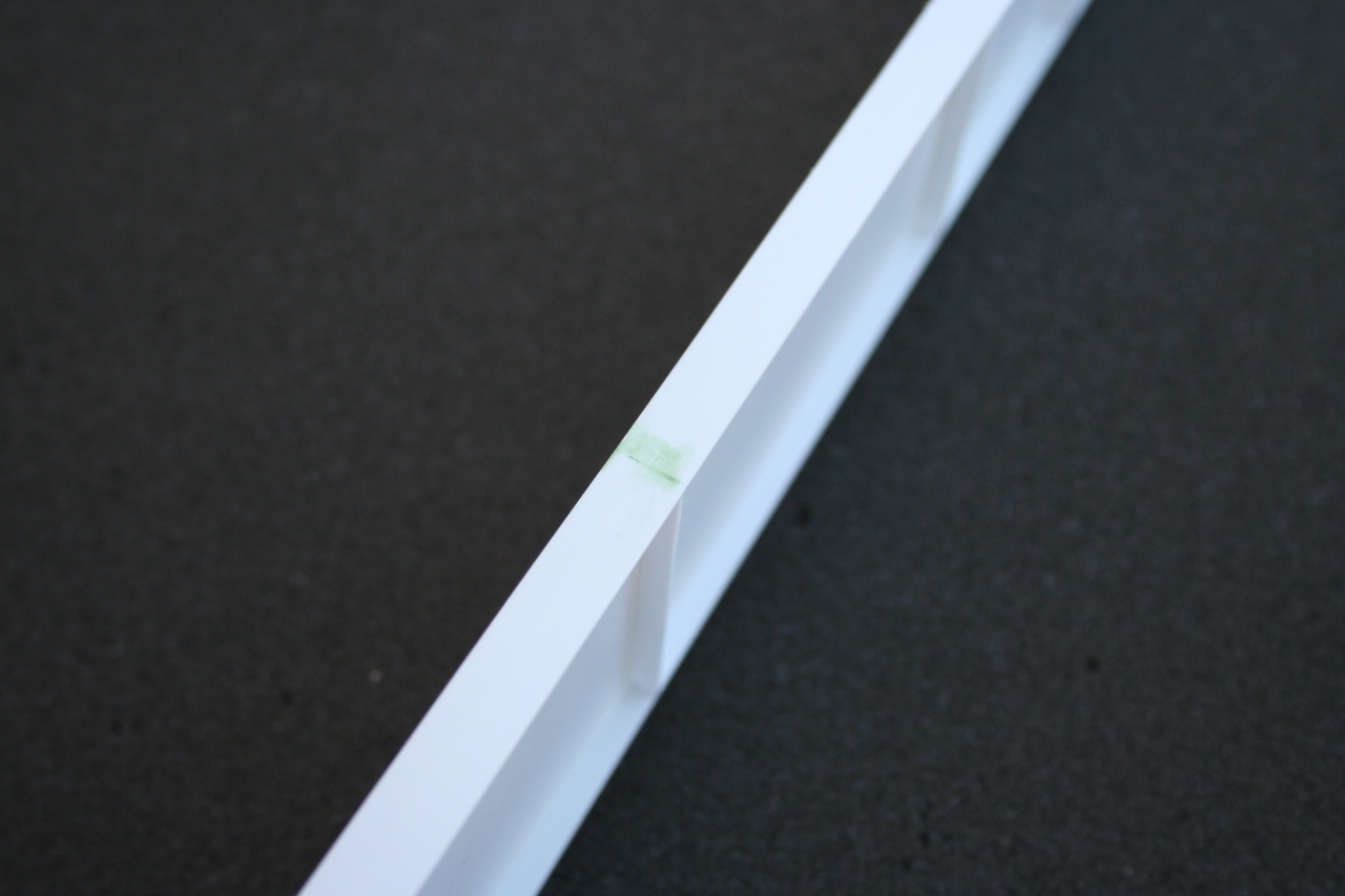
Wet sand the "Top Cap" of the beam with 400 grit sand paper to get a smooth finish.

Wet sand the "Bottom Cap" of the beam with 400 grit sand paper to get a smooth finish.
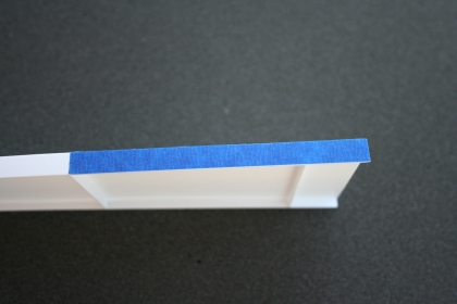
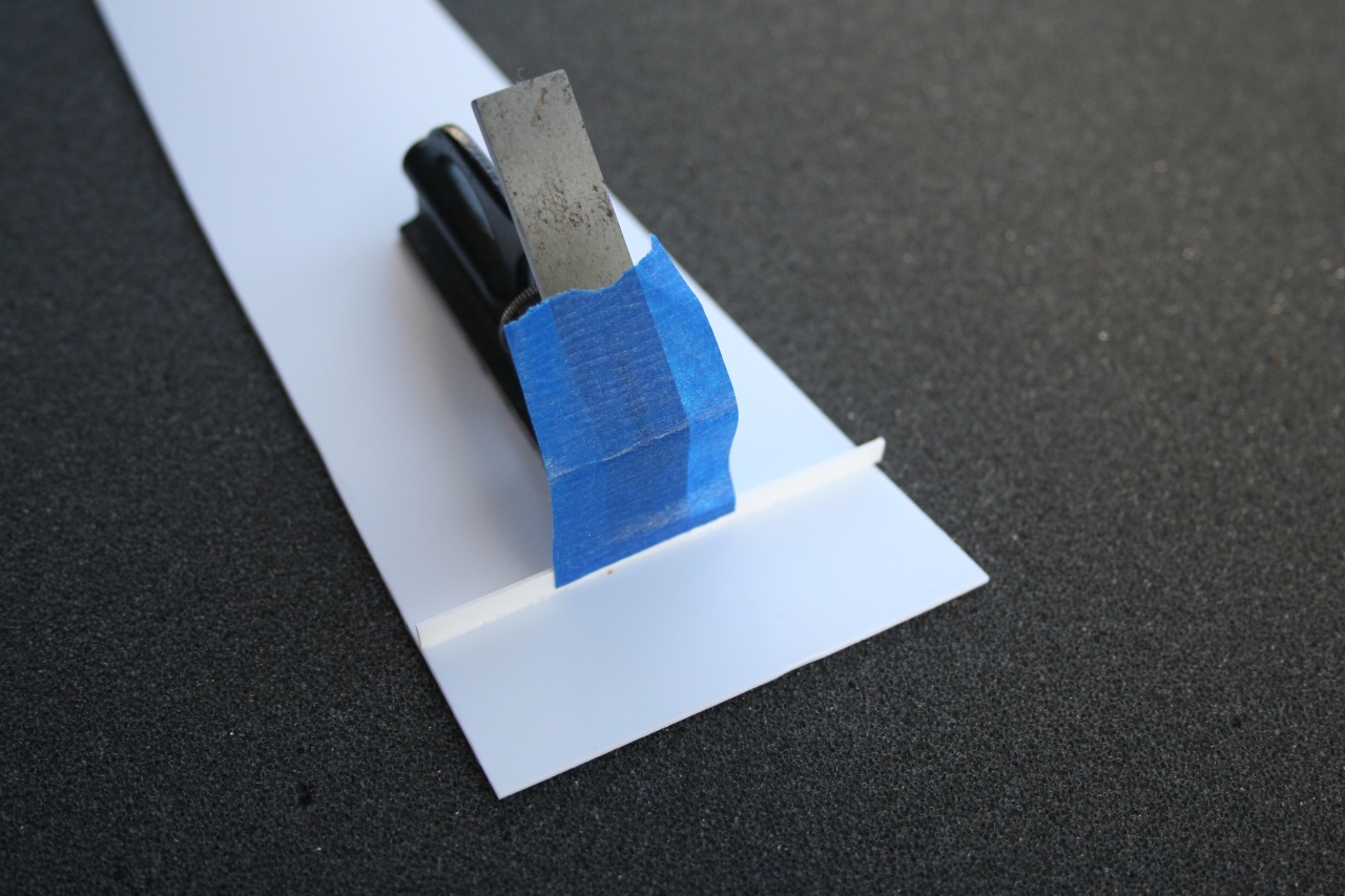
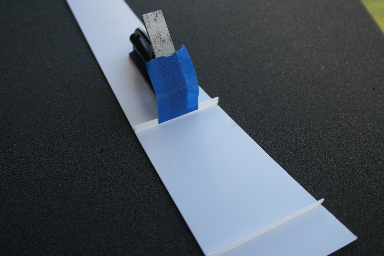
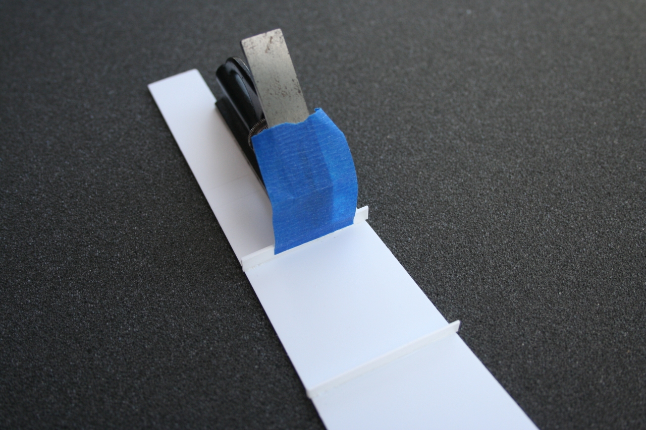
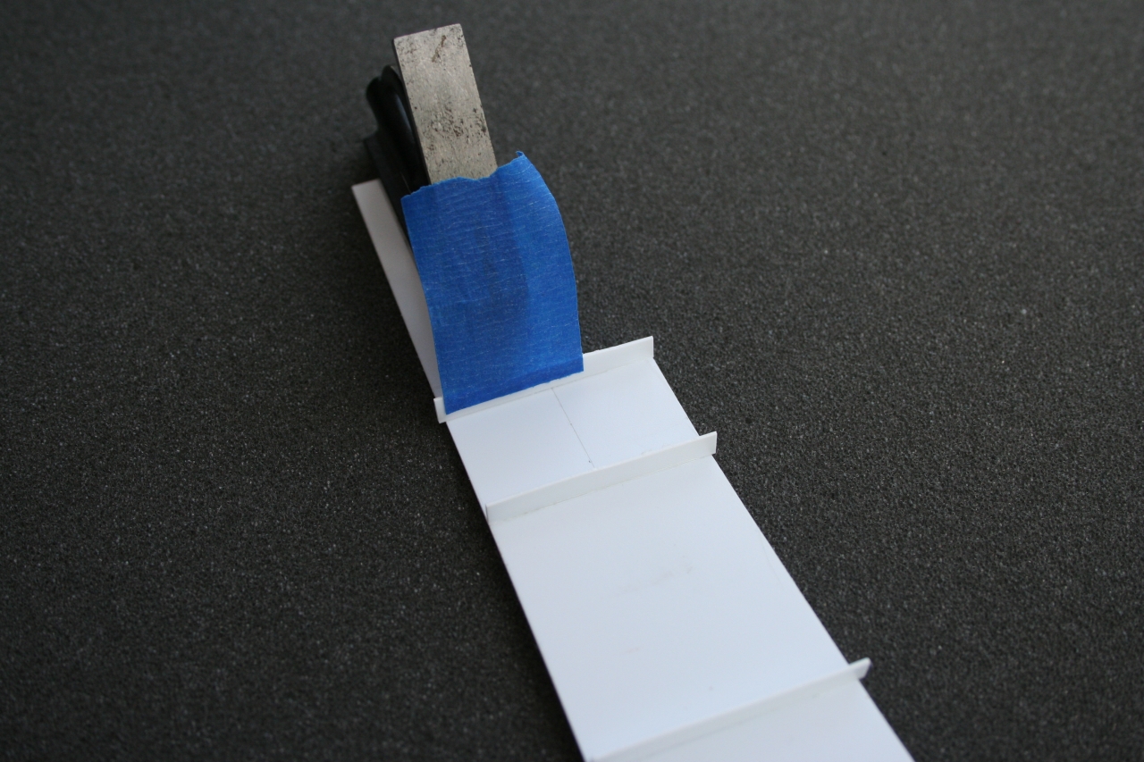
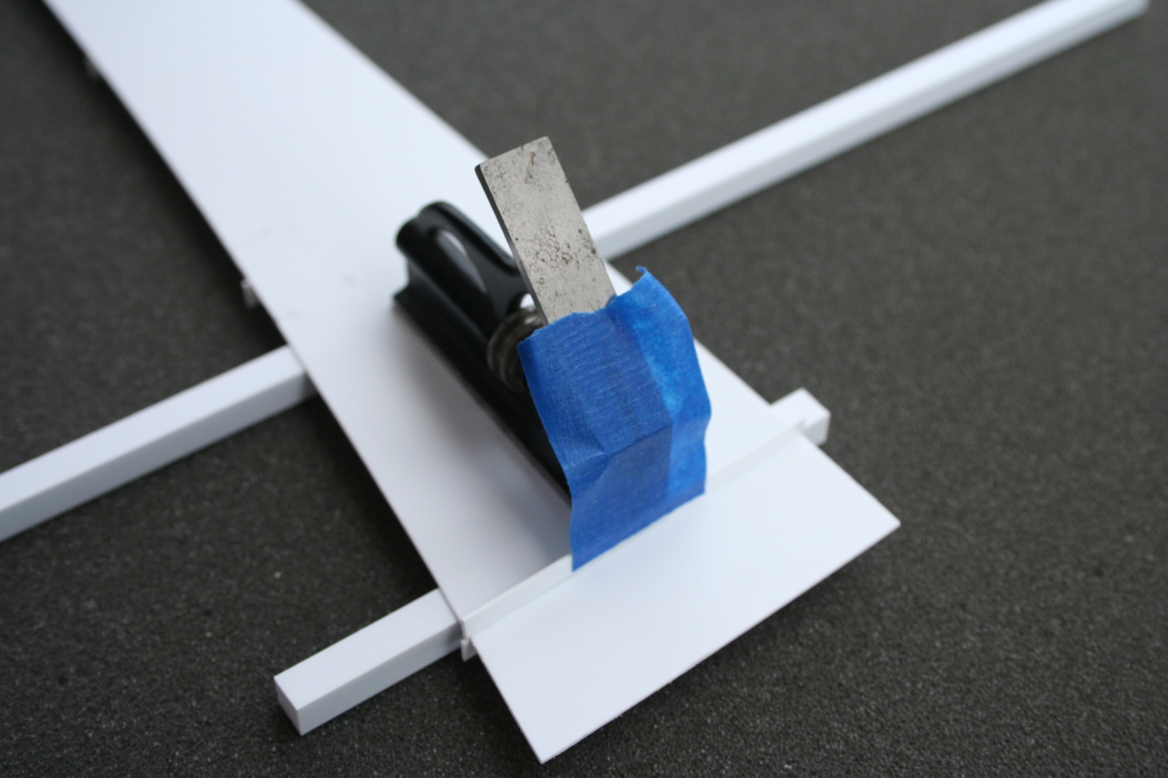
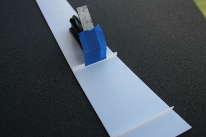
Use blue Painter's Tape to mask off the area on the bottom of the beam between the second vertical brace and the "Big End" of the beam. This is the area where the beam will be glued to the flatcar. Trim the tape as close to the beam as possible with out covering the sides of the beam. Do not remove the tape from the bottom of the beam until you are ready to glue the beam to the flatcar.
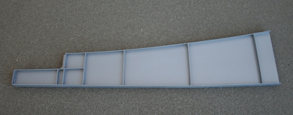
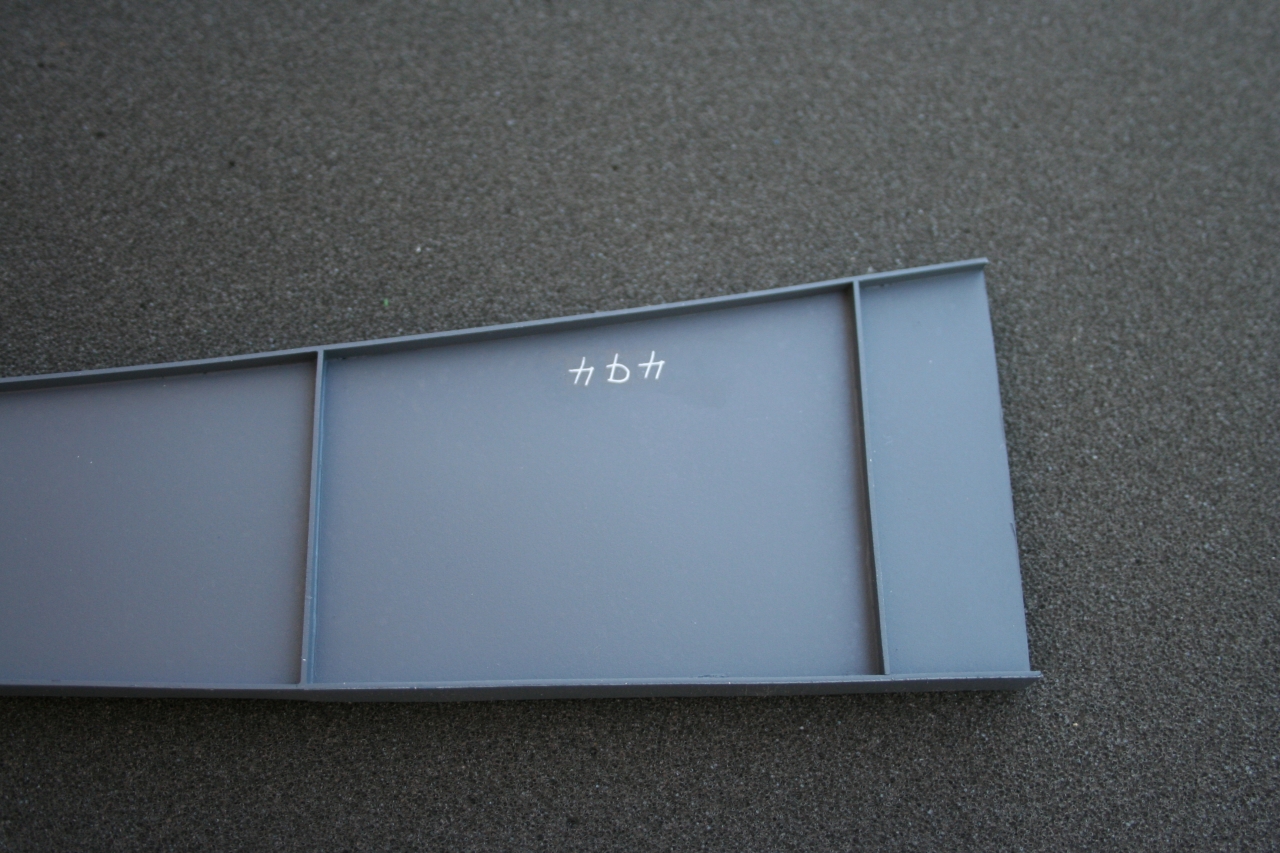
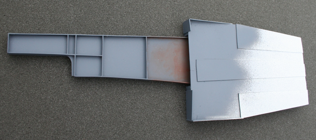
Paint the beam Gunship Gray.
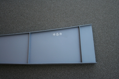
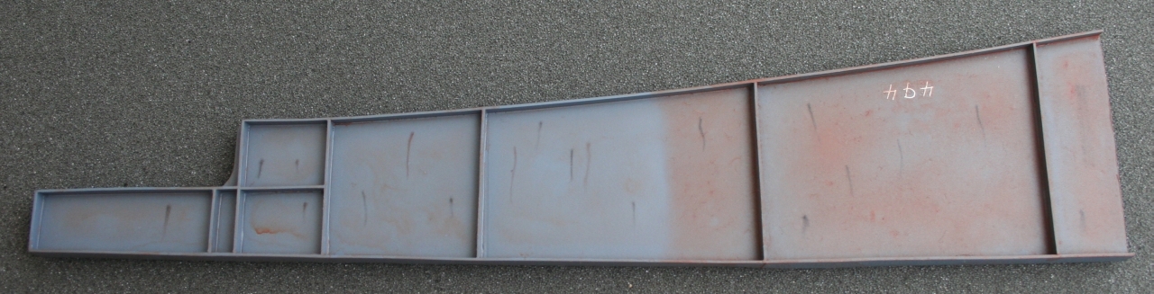
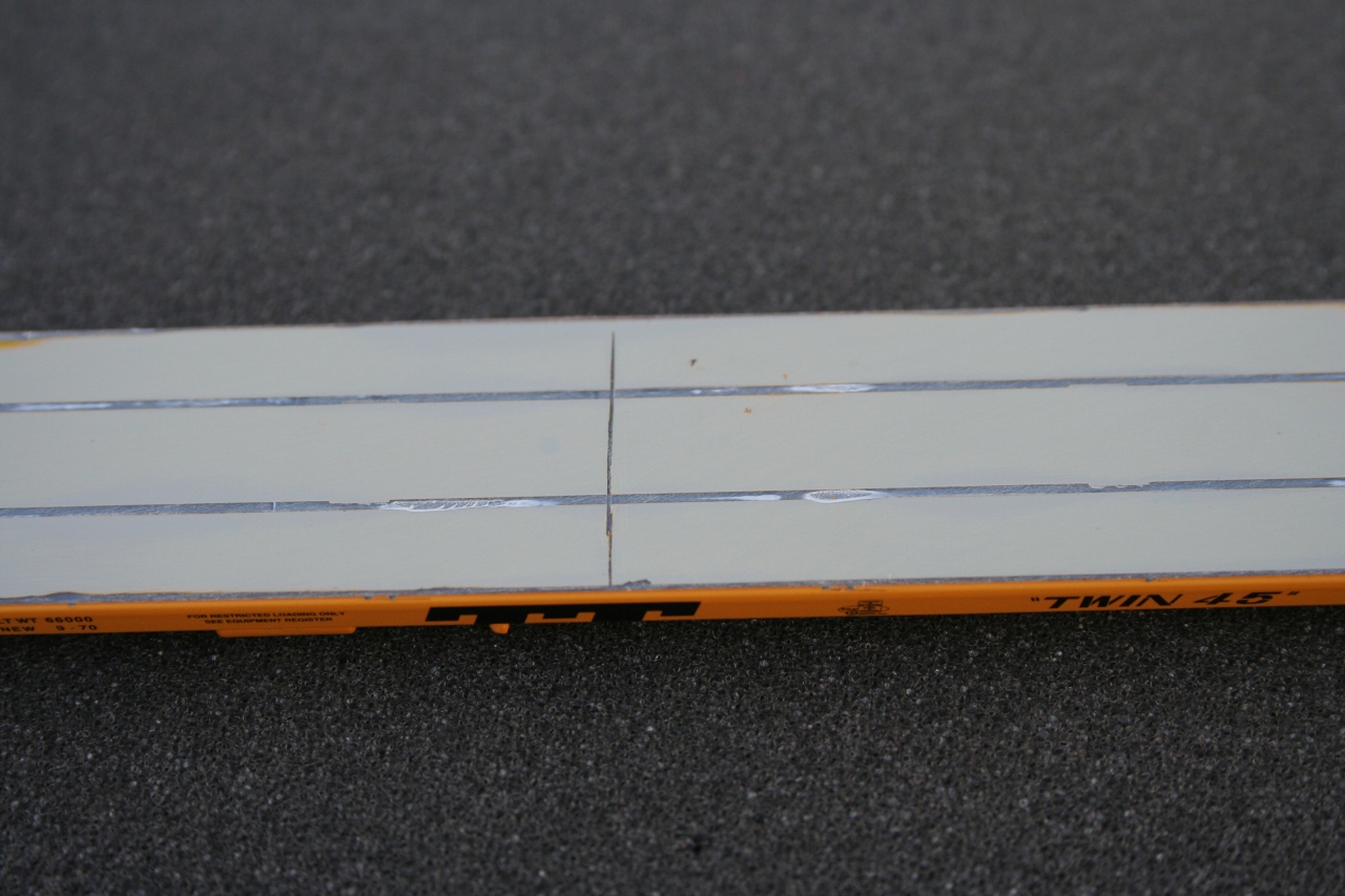
Add the "upside down" "494" and set with Solvaset.
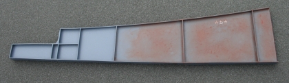
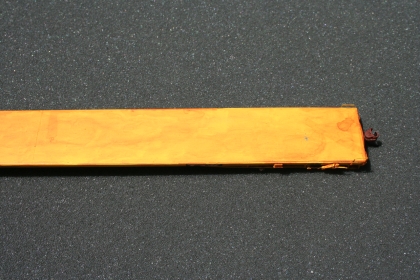
Cover the "Big End" of the beam to the third vertical brace with a heavy coat of Rust All. It may take more than one coat of Rust All to get the beam looking as rusty as you would like.

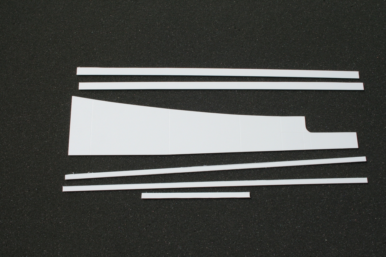
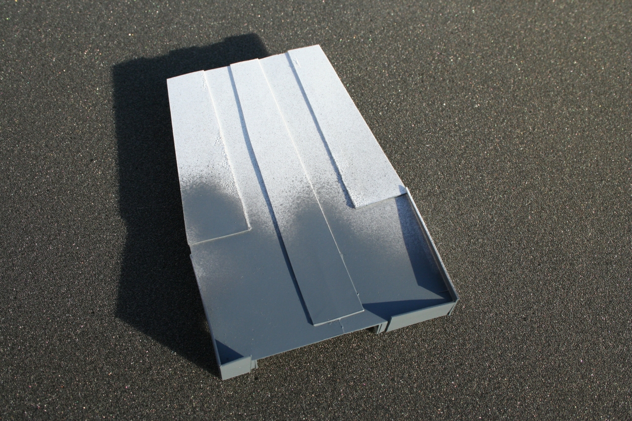
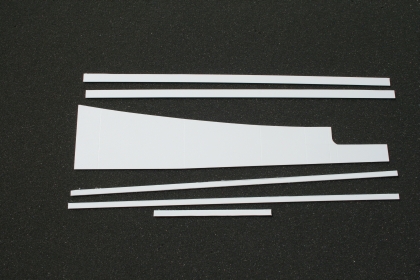
Build a paint mask out of scrap .030 plastic. This is a top view of the paint mask.
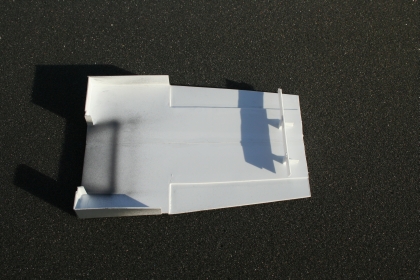
This is a bottom view of the paint mask.

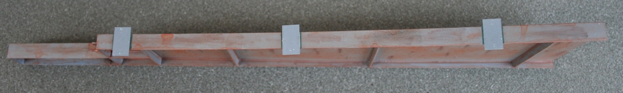
Beam with paint mask in place to.

Beam after repainting using the paint mask.

Use dark brown and black chalks to make vertical weathering marks.
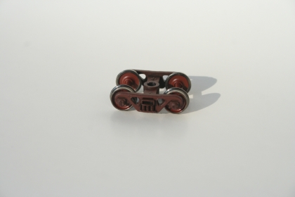
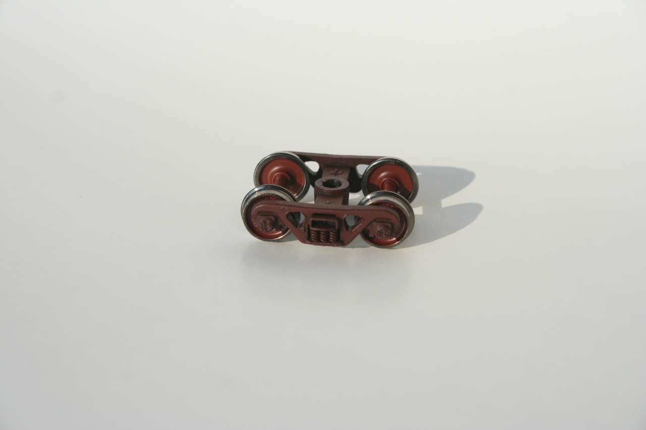
Paint the truck frames and wheel sets brown to give them the look of old weathered trucks and wheels. Don't paint the wheel tread or the outer lip of the tread. This gives the look of a wheel sets that have been through the retainers in hump yards.
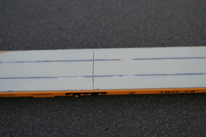
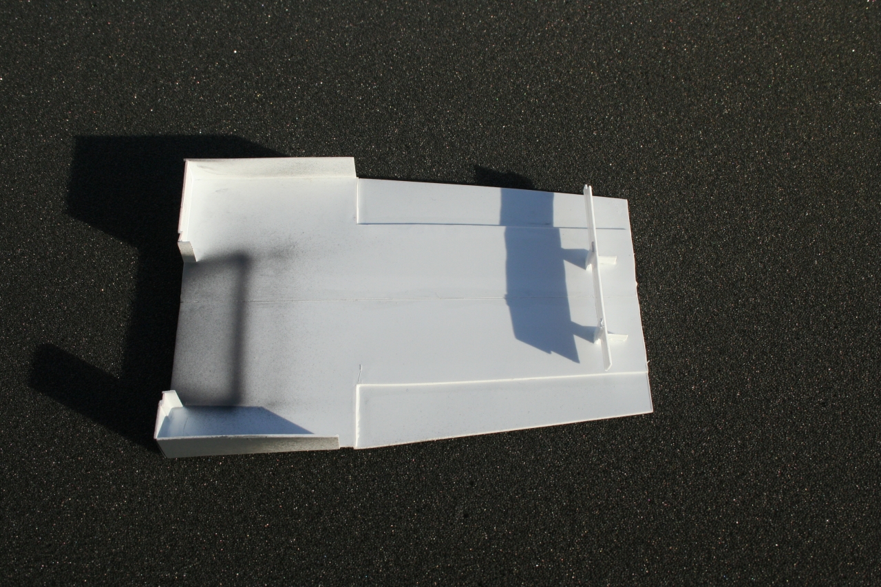
Remove the "rub rails" from the deck.
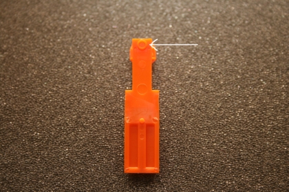
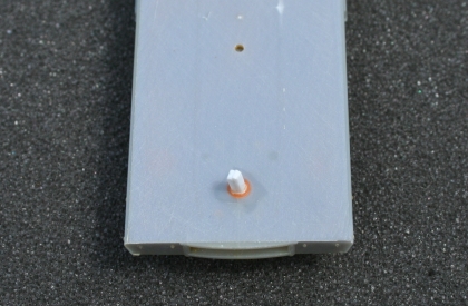
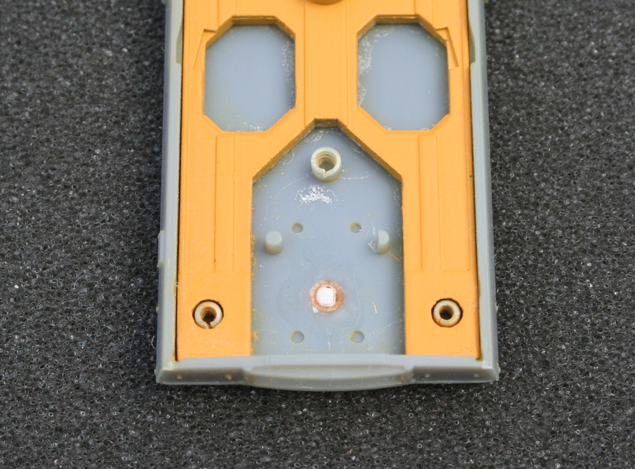
Remove this mounting circle. Use it to plug the hole in the deck where the trailer hitch was.

Glue the circle into the deck.
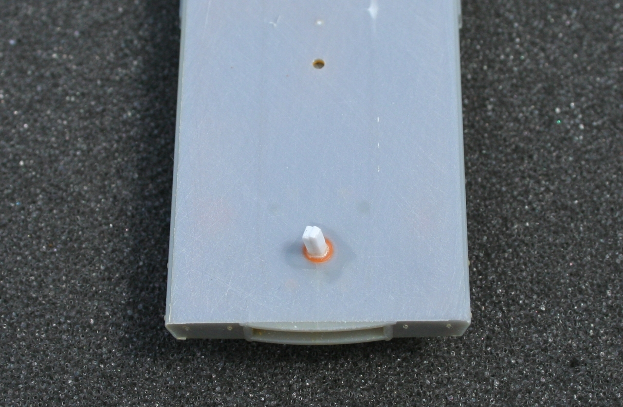
Plug the hole in the deck with a piece of .060 plastic. I used two pieces of .030 plastic glued together and cut to make a .060 square rod.

Cut the plug off flush with the deck.

Trim off the plug in the coupler area. This MUST be flush with the bottom of the deck.
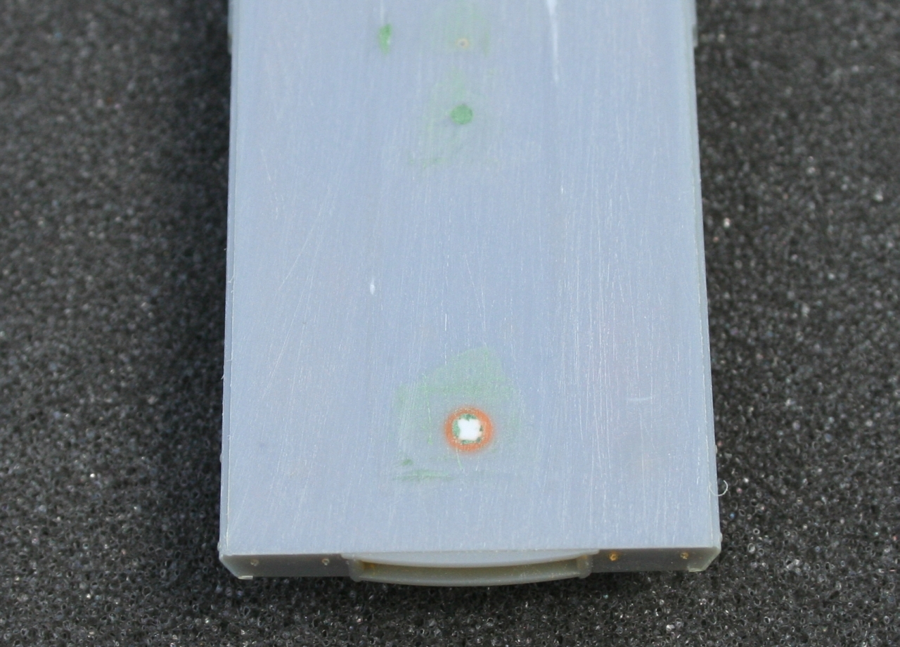
Fill all holes in the deck with Squadron Green putty.

Install grab irons and paint the model.
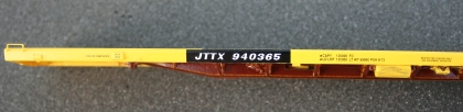
Placement of decals on the left side of the car.

Placement of decals on the right side of the car.

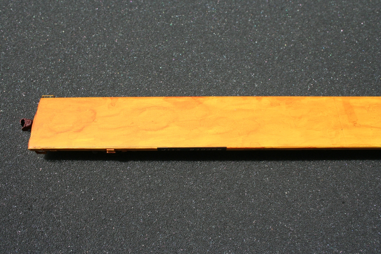
"A" end of car showing the weathering on the deck.
"B" end of car showing the weathering on the deck.
Glue tie down plates on top of beam. Use picture of prototype beam for placement.
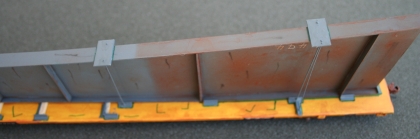
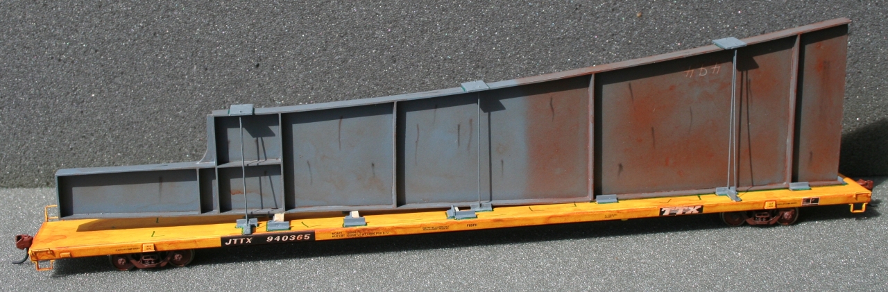
Remove the blue Painter's tape from the beam and glue the beam to the flatcar. Notice the angle iron and tie down rods.

Angle iron, dunnage, and tie down rods.
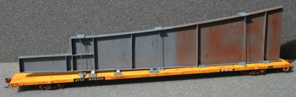
Finished model.
|

©2007-2023 B & FE Railroad Co. All rights reserved.
Last update to this page was July 29, 2012 |


